Программа для расчёта конструкций RFEM 6 является основой нашей модульной системы программного обеспечения. Основная программа RFEM 6 используется для задания конструкций, материалов и нагрузок плоских и пространственных конструктивных систем, состоящих из плит, стен, оболочек и стержней. Программа также позволяет создавать комбинированные конструкции, а также моделировать тела и контактные элементы.
RSTAB 9 - это мощная программа для расчёта и проектирования 3D конструкций балок, каркасов или ферм, которая которая помогает инженерам-строителям соответствовать современным требованиям и отражает последние тенденции в области строительного проектирования.
Вы часто тратите слишком много времени на расчёт сечений? Программное обеспечение Dlubal и автономная программа RSECTION облегчают вашу работу, определяя характеристики и выполняя расчёт напряжений для различных сечений.
Вы всегда знаете, откуда дует ветер? Конечно, со стороны инноваций! RWIND 2 - это программа, которая использует цифровую аэродинамическую трубу для численного моделирования потоков ветра. Программа моделирует эти потоки вокруг зданий любой геометрической формы и определяет ветровые нагрузки на поверхности.
Вам нужен обзор зон снеговой, ветровой и сейсмической нагрузок? Тогда вы находитесь по адресу. Используйте инструмент Geo-Zone Tool для быстрого и лёгкого определения снеговых нагрузок, скоростей ветра и данных по сейсмике в соответствии с ASCE 7‑16 и другими нормативами различных стран.
Хотите попробовать в работе функции программ Dlubal Software? У вас есть такая возможность! Бесплатная полная версия на 90 дней позволяет вам в полной мере попробовать в работе все наши программы.
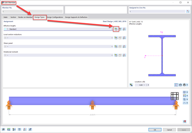
Для задания расчётных длин в RFEM 6 есть два варианта. First, edit the member and navigate to the "Design Types" Tab. Second, create a new effective lengths definition.
Third, set whether you would like to calculate the critical moment according to the Eigenvalue method or Chapter F from the AISC. Fourth, navigate to the "Nodal Supports and Effective Lengths" tab. Within this tab there are two different methods that can be used.
Метод 1: Узловые опоры и расчетные длины
Referencing Member No. 1 in the attached model, for this column you can see a how the effective lengths for the Start, End, and Intermediate nodes are defined. First, click on Select Member or Member Set and then select the member. This will activate the intermediate nodes along the member length in the table. Next, check whether the node can move in the y/z axis (weak/strong axis), rotate about its local x-axis (torsion), and about its local z-axis (LTB).
The Warping (ω) input options will adjust the effective length for LTB, similar to the rotational z-axis restraint. For Ch. F calculations, the warping can be fully restrained or released. For Eigenvalue calculations, in addition to the fully restrained or released option, there is also the ability to set partial fixity with a warping spring constant.
Top and bottom flanges can also be restrained separately by fixing the y-axis and by releasing (unchecking) the rotation about the local x-axis restraint (torsion).
Метод 2: "K" Factors and Absolute Values
Referencing Member No. 5 in the attached model, the effective length factors can be used to define the unbraced length directly and/or apply the appropriate member end conditions. To adjust the unbraced lengths directly instead of utilizing the nodes on the member (Method 1), the "K" factors can be entered manually in the table below. Or the "Absolute Values" can be entered by selecting the option "Absolute Values". Then the unbraced length itself can be entered manually instead. This method is best used when there are no intermediate nodes currently present on the member.
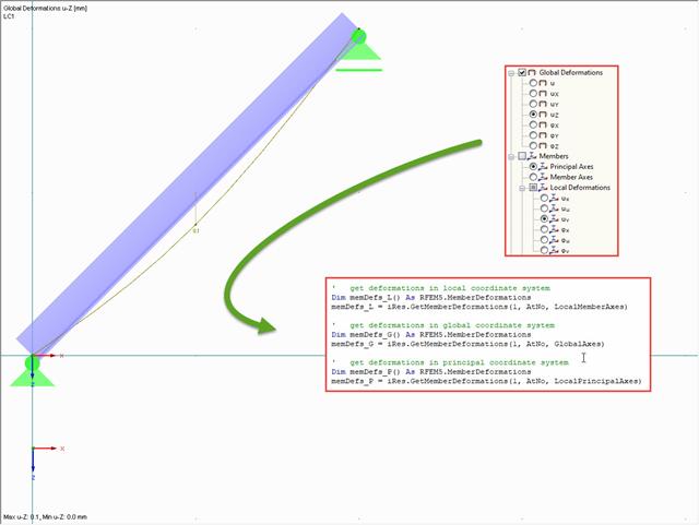
Деформации стержней можно считать, например, с помощью функции "GetMemberDeformations()". Однако эта функция ожидает указание номера, типа метода подсчета стержней (номер стержня/номер в списке) и то, какую систему координат следует использовать. Пользователь так может выбрать, будет ли использоваться местная система координат, система главных осей или общая система координат:
Sub test_results_member_axis()Dim iApp As RFEM5.ApplicationSet iApp = GetObject(, "RFEM5.Application")iApp.LockLicenseDim iMod As RFEM5.IModel3Set iMod = iApp.GetActiveModelOn Error GoTo e'get interface for calculationDim iCalc As RFEM5.ICalculation2Set iCalc = iMod.GetCalculation'get interface for resultsDim iRes As RFEM5.IResults2Set iRes = iCalc.GetResultsInFeNodes(LoadCaseType, 1)'get deformations in local coordinate systemDim memDefs_L() As RFEM5.MemberDeformationsmemDefs_L = iRes.GetMemberDeformations(1, AtNo, LocalMemberAxes)'get deformations in global coordinate systemDim memDefs_G() As RFEM5.MemberDeformationsmemDefs_G = iRes.GetMemberDeformations(1, AtNo, GlobalAxes)'get deformations in principal coordinate systemDim memDefs_P() As RFEM5.MemberDeformationsmemDefs_P = iRes.GetMemberDeformations(1, AtNo, LocalPrincipalAxes)e:If Err.Number <> 0 Then MsgBox Err.description, vbCritical, Err.SourceiMod.GetApplication.UnlockLicenseSet iMod = NothingEnd Sub
Эта небольшая программа способна считать местные деформации (memDefs_L) в осях стержня и главных осях (memDefs_P), а также общие деформации в осях стержня (memDefs_G).
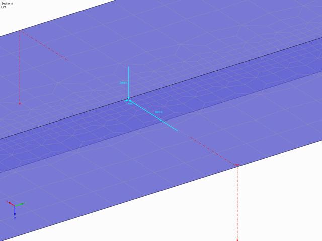
Как и все остальные результаты, результирующую сечения можно считывать с помощью команды IModel3 → ICalculation2 → IResults2. Интерфейс результатов обеспечивается посредством функции GetResultant, которая при указании номера желаемого сечения и типа распределения результатов способна вернуть структуру ResultantForce. В данной структуре отображаются, среди прочего, также силы и моменты в виде векторов:
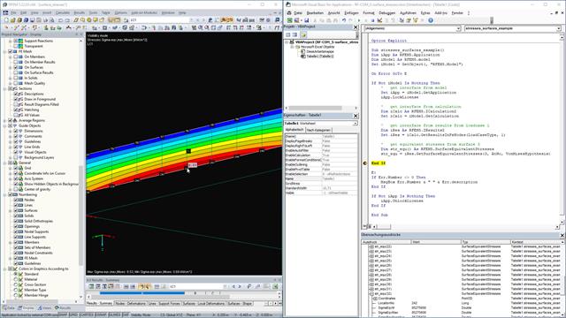
Да, напряжения на поверхности можно отобразить также через интерфейс COM. Однако для этого вам потребуется сначала интерфейс для модели (IModel), а потом интерфейс для расчета (ICalculation2). С помощью данного интерфейса затем можно получить интерфейс для результатов (IResults2):
Sub stresses_surfaces_example()Dim iApp As RFEM5.ApplicationDim iModel As RFEM5.modelSet iModel = GetObject(, "RFEM5.Model")On Error GoTo EIf Not iModel Is Nothing Then' get interface from modelSet iApp = iModel.GetApplication iApp.LockLicense ' get interface from calculation Dim iCalc As RFEM5.ICalculation2 Set iCalc = iModel.GetCalculation ' get interface from results from loadcase 1Dim iRes As RFEM5.IResults2 Set iRes = iCalc.GetResultsInFeNodes(LoadCaseType, 1) ' get equivalent stressesDim str_equ() As RFEM5.SurfaceEquivalentStressesstr_equ = iRes.GetSurfaceEquivalentStresses(1, AtNo, VonMisesHypothesis) End IfE:If Err.Number <> 0 ThenMsgBox Err.Number & " " & Err.descriptionEnd IfIf Not iApp Is Nothing Then iApp.UnlockLicenseEnd If
Функция GetSurfaceEquivalentStresses затем требует задания расчетной гипотезы. В данном примере у нас будут отображать результаты напряжения по фон Мизесу. Не забудьте, что в интерфейсе COM используются единицы SI, поэтому напряжение передается всегда в Н/м².
Sub test_section()' get interface from the opened model and lock the licence/program Dim iModel As RFEM5.IModel3 Set iModel = GetObject(, "RFEM5.Model") iModel.GetApplication.LockLicense On Error GoTo E Dim iSecs As RFEM5.ISections Set iSecs = iModel.GetSections()
' first delete all sections iSecs.PrepareModification iSecs.DeleteObjects ("All") iSecs.FinishModification ' set section on solid Dim sec As RFEM5.Section sec.EdgePointA.X = 2 sec.EdgePointA.Y = 5 sec.EdgePointA.Z = 0 sec.EdgePointB.X = 2 sec.EdgePointB.Y = 8 sec.EdgePointB.Z = 0 sec.no = 1 sec.Name = "solid section" sec.Plane = GlobalPlaneInPositiveX sec.ShowValuesInIsolines = False sec.Type = SectionOnSolidSectionLine sec.ObjectList = "1" iSecs.PrepareModification iSecs.SetSection sec iSecs.FinishModification
' set section on surface sec.EdgePointA.X = 2 sec.EdgePointA.Y = 0 sec.EdgePointA.Z = 0 sec.EdgePointB.X = 2 sec.EdgePointB.Y = 3 sec.EdgePointB.Z = 0 sec.no = 2 sec.Name = "surface section" sec.Plane = GlobalPlaneInPositiveX sec.ShowValuesInIsolines = True sec.Type = SectionViaSurfacePlane sec.ObjectList = "1" sec.Vector.X = 0 sec.Vector.Y = 0 sec.Vector.Z = 1 iSecs.PrepareModification iSecs.SetSection sec iSecs.FinishModification
' get results Dim iCalc As ICalculation2 Set iCalc = iModel.GetCalculation Dim iRes As IResults2 Set iRes = iCalc.GetResultsInFeNodes(LoadCaseType, 1) Dim secRes() As RFEM5.SectionResult secRes = iRes.GetResultsInSection(2, AtNo, ShearForceVy,ContinuousDistributionWithinObjects, False)